Capacitors
Information and tips about capacitors
Voltage derating
Tantalum with MNO2 dielectric
Maximum voltage shall not excess in any case rated voltage.
Application continuous voltage shall be maximum 50% of rated voltage.
Maximum current shall be caculated carefully
Conductive polymer
Maximum voltage shall not excess in any case rated voltage.
A 90% derating shall be used if voltage rating of the capacitor is 10V or lower.
A 80% derating shall be used if voltage rating of the capacitor is 16V or higher.
Ceramic / MLCC
Maximum voltage shall not excess in any case rated voltage
No derating required
Aluminium
Maximum voltage shall not excess in any case rated voltage
No derating required
Operating temperature will greatly affect lifetime, power dissipation shall be verified.
Guideline for MLCC
This is a guideline for ceramic SMT capacitors when designing PCB.
General idea is to use X7R or X5R dielectric type.
Maximum values by package and voltage
0201
- 10 nF 10 V
- 1 nF 25 V
0402
- 1 µF 10 V
- 220 nF 16 V
- 100 nF 25 V
0603
- 10 µF 6.3 V
- 2.2 µF 10 V
- 1 µF 25 V
0805
- 10 µF 10 V
- 4.7 µF 25 V
1206
- 100 µF 6.3 V
- 22 µF 16 V
- 10 µF 25 V
1210
- 47 µF 16 V
- 22 µF 25 V
MLCC capacitors dielectric
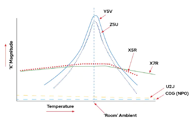
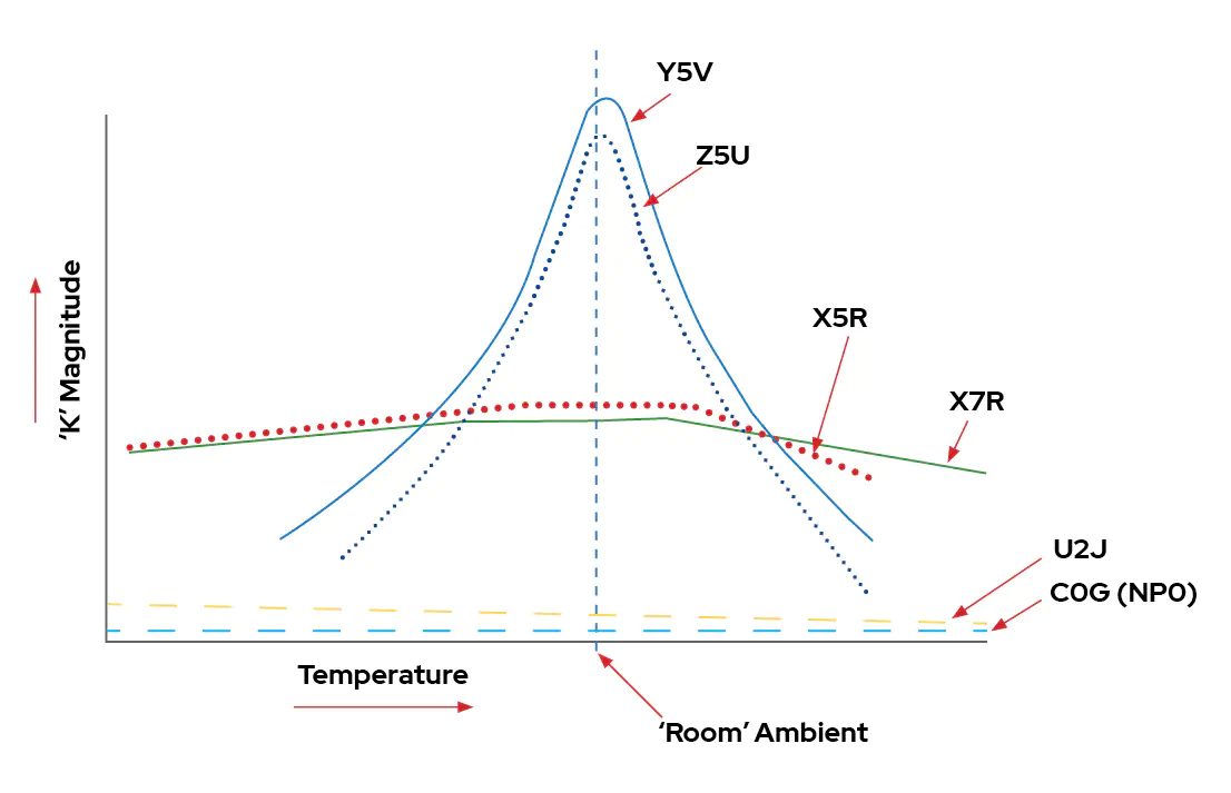
MLCC capacitors are sorted in three different classes depending on the dielectric.
Common dielectrics are C0G, X5R, Z5U
For class 2 and class 3, dielectric is defined by three two letters and one number :
- First character defines the lowest temperature
- Second character defines the maximum temperature
- Third character defines the capacitance variation over whole temperature range
Here is chart showing capacitance variation depending on temperature :
Class 1 C0G, U2J
Class 1 capacitors are “ultra-stable”, this class of capacitors is suitable for oscillators, clocks, analog chains where precision is required.
Theses capacitors are not affected by piezoelectric singing effect.
Maximum value is 1nF
Common dieletrics are C0G, U2J
| First Character | Temperature coefficient (ppm/°C) | Second character | Temperature coefficient multiplier | Third character | Tolerance of temperature coefficient (ppm/°C) |
|---|---|---|---|---|---|
| C | 0 | 0 | -1 | G | 30 |
| B | 0.3 | 1 | -10 | H | 60 |
| L | 0.8 | 2 | -100 | J | 120 |
| A | 0.9 | 3 | -1000 | K | 250 |
| M | 1.0 | 4 | -10000 | L | 500 |
| P | 1.5 | 5 | +1 | M | 1000 |
| R | 2.2 | 6 | +10 | N | 2500 |
| S | 3.3 | 7 | +100 | ||
| T | 4.7 | 8 | +1000 | ||
| U | 7.5 | 9 | +10000 |
Class 2 X7R, X5R, X6S
Class 2 capacitors are general use bulk and bypass capacitors.
Theses capacitors are affected by pizoelectric singing effect.
Maximum value is 100uF
Common dieletrics are X7R, X5R, X6S
| First Character | Low temperature (°C) | Second character | High temperature (°C) | Third character | Tolerance of temperature coefficient (%) |
|---|---|---|---|---|---|
| Z | +10 | 2 | +45 | A | +/- 1.0 |
| Y | -30 | 4 | +65 | B | +/- 1.5 |
| X | -55 | 5 | +85 | C | +/- 2.2 |
| 6 | +105 | D | +/- 3.3 | ||
| 7 | +125 | E | +/- 4.7 | ||
| 8 | +150 | F | +/- 7.5 | ||
| 9 | +200 | P | +/- 10 | ||
| R | +/- 15 | ||||
| S | +/- 22 | ||||
| L | +15 to -40 | ||||
| T (class 3) | +22 to -33 | ||||
| U (class 3) | +22 to -56 | ||||
| V (class 3) | +22 to -82 |
Class 3 Z5U and Y5V
Class 3 capacitor are reserved for very low cost application. Generally class 3 capacitors shall be avoided except if you know what you are doing or you want to optimize every cent of your design
Theses capacitors are affected by pizoelectric singing effect.
Maximum value is 100uF
Piezoelectric effect
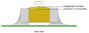
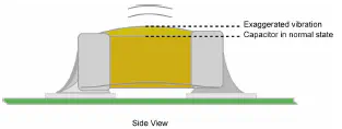
Sometimes capacitor are producing sound. Voltage and current inside capacitor can make it vibrate. This is mainly caused by voltage ripple and current ripple. Capacitors making sound happens when current ripple frequency is in the audio band (20Hz to 20kHz). This is something classic when DC/DC are in light load mode (pulse skipping).
Class 2 and Class 3 capacitors are concerned by this effect. Class 1 capacitors does not produce it
Source links
MLCC Dielectric differences on Kemet blog


